
Solving Problems in Qualifying Weld Procedures
Many fabricators encounter difficulties in qualifying welding procedures or welders for aluminum. Most codes require the use of reduced section tensile tests and guided bend tests for procedure qualification. Therefore, we will discuss these two requirements:
Difficulties in Meeting Tensile Test Requirements
All codes have minimum tensile test values. Samples removed from procedure qualification test plates must meet these values.
However, the weld does not have to meet the same minimum requirements as the parent material. For example, all codes require that 6061–T6 material have a minimum tensile strength of 40 ksi (276 MPa). Welds in 6061–T6 only have to meet 24 ksi (165 MPa) minimum. It is important to understand what is required for the specific alloy being used.
There are several reasons why samples fail tensile testing. For heat-treatable alloys, usually it is because excessive heat input has been used. Common reasons for excessive heat input are:
- Use of excessive preheat. Preheat should be no more than 200°F (93°C) and isn’t needed unless the ambient temperature is below 32°F (0°C).
- Interpass temperature that is too high. Maximum interpass temperature should be 250°F (121°C).
- Technique issues, such as the use of very wide weave passes, which can cause heat input to be excessive.
Generally stringer passes should be used, although weaving is acceptable as long as the weave width is no wider than four times the wire diameter.
Weld defects can also cause premature tensile failures. Observe the fracture face of the failed tensile sample. The presence of weld defects should be fairly obvious. Lack of fusion or lack of penetration defects are especially prone to cause tensile failure.
Where the code requires the tensile sample to meet 40 ksi (276 MPa) minimum tensile strength, the use of 5356 is not recommended. Higher strength filler alloys, such as 5183 or 5556, are recommended for these applications.
Difficulties in Meeting Bend Test Requirements
Most bend test failures are caused by the welder’s lack of familiarity with the bend test requirements for aluminum welds.
Some points to remember are as follows:
- The ductility of aluminum welds is lower than that of steel welds. Ensure the test radius is correct for the alloy under test. Figure 1 below shows the bend test requirements of AWS D1.2.
- If the bend sample fails with little or no distortion before breaking, the most likely cause is a defect in the weld. Any lack of fusion or insufficient penetration in the weld will quickly open up on bending and cause the sample to break in half. A visual examination of the fracture surface will reveal these defects.
- Ensure that the bend test sample preparation is correct. a. Make sure grinding or machining marks go along the length of the sample, not across it. Marks going across the sample can act as crack initiation sites. b. Don’t leave square-machined corners on the sample. All codes allow a radius at the corners of 1/2 the sample thickness or 1/4” (6.4 mm), whichever is less. Adhering to this radius reduces the probability of initiating a crack in the corners.
- Special precautions are necessary when testing welds in 6061 or other M23 (per AWS) or P23 (per ASME Section IX) materials because of their limited ductility. In recognition of this, both AWS D1.2 and ASME Section IX require bend test samples in 6061 and other M23 materials to be machined to 1/8″ (3.2 mm) thickness, instead of the normal 3/8″ (9.5 mm) thickness. If 6061 samples are machined to 3/8″ (9.5 mm) thickness and tested around a standard radius mandrel, they often fail. AWS D1.2 alternatively allows samples in M23 materials to be machined to 3/8″ (9.5 mm) thick and annealed before testing, but ASME Section IX has no such provision.
- The use of the standard plunger-type bend tester is responsible for most bend test failures. This test fixture works well for steel because the mechanical properties of the weld, HAZ, and parent material are all similar. However, in aluminum, the HAZ’s are usually much weaker than the remainder of the sample. If the sample is tested in a plunger–type tester, the bend strain is concentrated in the HAZ. Instead of bending smoothly around the mandrel, the sample often forms a sharp kink at the HAZ and the sample fails at the kink.
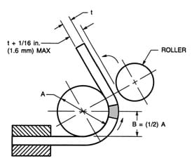
A much better test for welded aluminum bend samples is the Wraparound Guided Bend Test, shown. In this test, the sample is pulled around the mandrel and forced to stay in contact with it. These test jigs are often made from rotary tubing benders. Both AWS D1.2 and ASME Section IX encourage the use of these testers for aluminum.
| Thickness of Specimen Inches | A (Inches) | B (Inches) | Materials |
| 3/8
T |
1-1/2\
4t |
3/4
2t |
M21 and M22 |
| 1/8
T(<1/8) |
2-1/16
16-1/2t |
1-1/32
8-1/4t |
M23 and F23 Welds |
| 3/8
T |
2-1/2t
6-2/3t |
1-1/4
3-1/3t |
M25 and Annealed M23 |
| 3/8
T |
3
8t |
1-1/2
4t |
M27 and Annealed M24 |
Notes:
- Dimensions not shown are the option of the designer. The essential consideration is to have adequate rigidity so that the jig parts will not springs.
- The specimen shall be firmly clamped on one end so that there is no sliding of the specimen during the bending operation.
- Test specimens shall be removed from the jig when the outer roll has been removed 180° from the starting point.